Machines
Tube Expander (No-Shrinkage Type)
Contact for quote
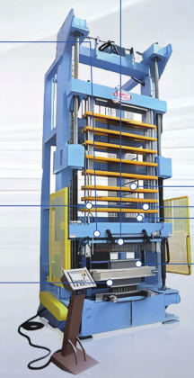
A servo-driven, flip-door vertical tube expander using forced (no-shrinkage) expansion — clamping both tube ends before expanding cuts shrinkage by about 2.5% versus ordinary expansion.
This vertical, flip-door tube expander uses a forced (no-shrinkage) expansion method: both ends of the copper tube are clamped before expanding, which cuts tube shrinkage by roughly 2.5% compared to ordinary expansion. It expands and flares copper heat-exchanger tubes (expand, then a second and third flare) so the tube grips the fins and end plates tightly for full heat-transfer contact.
Construction: a welded, stress-relieved steel frame carries two ball screws and two precision linear guides; the expanding crossbeam is servo-driven with linear-guide blocks for vertical accuracy. Expanding rods are all pre-loaded on the machine on a tool-free storage beam — changing product type only needs the operator to select and lock the required rods on the touchscreen, without removing any rods, saving changeover time. Guide plates are CNC machining-center finished for accurate rod/head entry into the tube. An adjustable ball-screw mechanism resets the working height for different heat-exchanger sizes. The worktable flips between horizontal (load) and vertical (expand) positions; front/rear door panels are manually swapped per row count, with a separate slide-door option for parts under 1.2m (the two door types don't interfere with each other). Upper clamping is motor-driven; lower clamping is pneumatic with a spring-return U-lock, plus a separate cylinder that holds the flip-door panel steady during expansion and another that ejects the finished workpiece from the U-clamp afterward. A servo-driven scanning flare head sets flare depth digitally to about 1‰ accuracy based on workpiece height. Tooling (rods, heads, flare punches, spring collets, flare dies, self-locking U receivers and straight-tube receivers) is built to the customer's exact tube spec. A rod-deflection monitor alarms and stops the machine if a rod bends past its limit.
Control: PLC + touchscreen, with manual per-station and full-auto modes, alarm indication (power, cycle complete, low oil, abnormal cycle, e-stop, thermal trip), e-stop buttons at both ends of the machine, and light-curtain/laser-radar guarding on the flip door. Automatic timed, metered lubrication feeds all moving parts.
Key components: Mitsubishi PLC and touchscreen; Airtac cylinders and solenoid valves; Inovance/Leadshine drive motors and Inovance servo system; Omron/Schneider proximity switches and low-voltage electricals; TBI/Dinghan linear guides; HRB/NSK bearings.
Example specification (from one completed build — tube diameter, row/hole count and overall dimensions are engineered to each order's exact heat-exchanger design, so treat the figures below as representative of capability, not a fixed catalog spec):
Expansion height range 200–2000mm; example tube sizes φ7.2×0.28+0.15mm (internally grooved) and φ5×0.2mm plain / φ5×0.2+0.15mm grooved; example fin hole diameters φ7.5mm / φ5.2mm; up to 5 rows × 54–55 holes (21mm pitch, 21.65mm row pitch) or 5 rows × 66–67 holes (20mm pitch, 17.32mm row pitch); up to 350 holes per expansion stroke on ≤0.5mm wall tube, 200 holes on ≥0.5mm wall; supports both U-tube and straight tube (the no-shrinkage benefit applies to U-tube; straight tube runs with normal shrinkage); expansion speed 8 m/min; flip-door cycle ≤25s; overall cycle time under 120s at 2000mm length (excludes load/unload); overall footprint approximately 2400 × 2600 × 7500mm (L×W×H), around 15 tons.
Acceptance-grade precision on this build: end-plate parallelism ≤0.8mm (workpiece width ≤800mm) or width/1000 beyond that; flatness ≤0.8mm up to 800mm length, ≤1mm from 800–1200mm, ≤2mm beyond 1200mm; length tolerance ≤1.2mm up to 1200mm or length/1000 beyond that; flare-to-expansion concentricity ≤Φ0.2mm.
Ask us for your tube diameter, row count and target cycle time — each expander is engineered to the job.
Request a Quote for This ItemTechnical Specifications
| Note | Example specification from a completed build — engineered per order |
|---|---|
| Expansion Type | Forced / no-shrinkage (~2.5% less shrinkage) |
| Example Model | LSZ-F7*F5-21*5/200L |
| Expansion Height Range | 200–2000mm |
| Example Tube Sizes | φ7.2×0.28+0.15mm grooved; φ5×0.2mm plain / φ5×0.2+0.15mm grooved |
| Example Fin Hole Diameter | φ7.5mm / φ5.2mm |
| Max Rows × Holes (Example) | 5×54–55 (21/21.65mm pitch) or 5×66–67 (20/17.32mm pitch) |
| Max Holes per Stroke | 350 (wall ≤0.5mm) / 200 (wall ≥0.5mm) |
| Tube Types Supported | U-tube and straight tube |
| Expansion Drive | Servo motor |
| Expansion Speed | 8 m/min |
| Flare Method | Scanning flare after expansion, ~1‰ depth accuracy |
| Flip-Door Cycle | ≤25s |
| Cycle Time (Example, L=2000mm) | < 120s (excludes load/unload) |
| Max Rows Supported | 5 |
| Overall Dimensions (Example) | 2400 × 2600 × 7500mm (L×W×H) |
| Approx. Weight (Example) | ~15 tons |
| Power Supply | 3-phase 380V ±10%, ≤22kW |
| Compressed Air | 0.4–0.6MPa |
| End-Plate Parallelism | ≤0.8mm (≤800mm width) or width/1000 |
| Flatness | ≤0.8–2mm depending on length |
| Flare-to-Expansion Concentricity | ≤Φ0.2mm |
More from Machines
machines
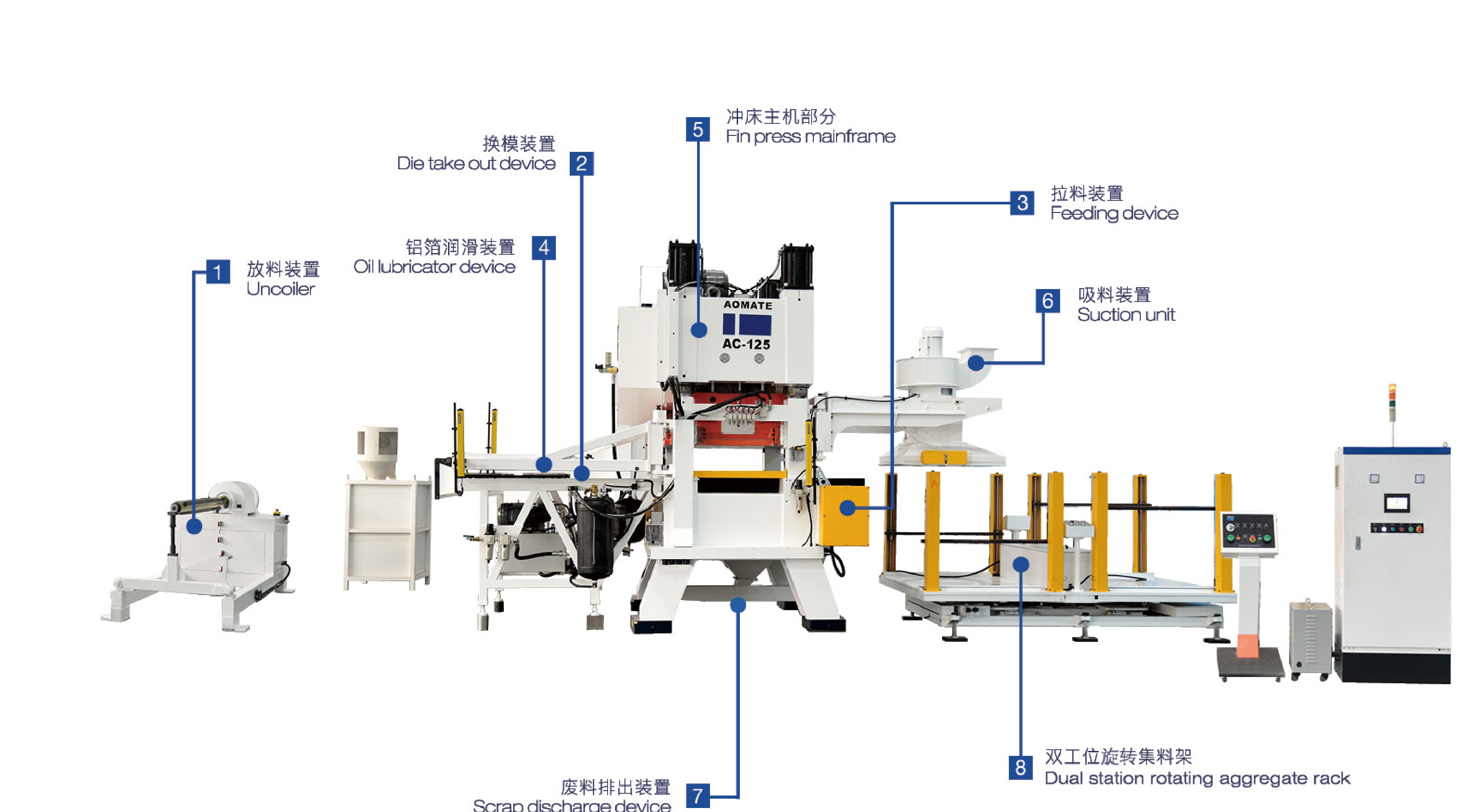
AC Series Automatic Fin Press Line (High-Speed, Parallel/Dual-Shaft)
A complete high-speed automatic fin press production line for air-conditioning/refrigeration fins, from coil uncoiler through to dual-station finished-fin collection.
machines
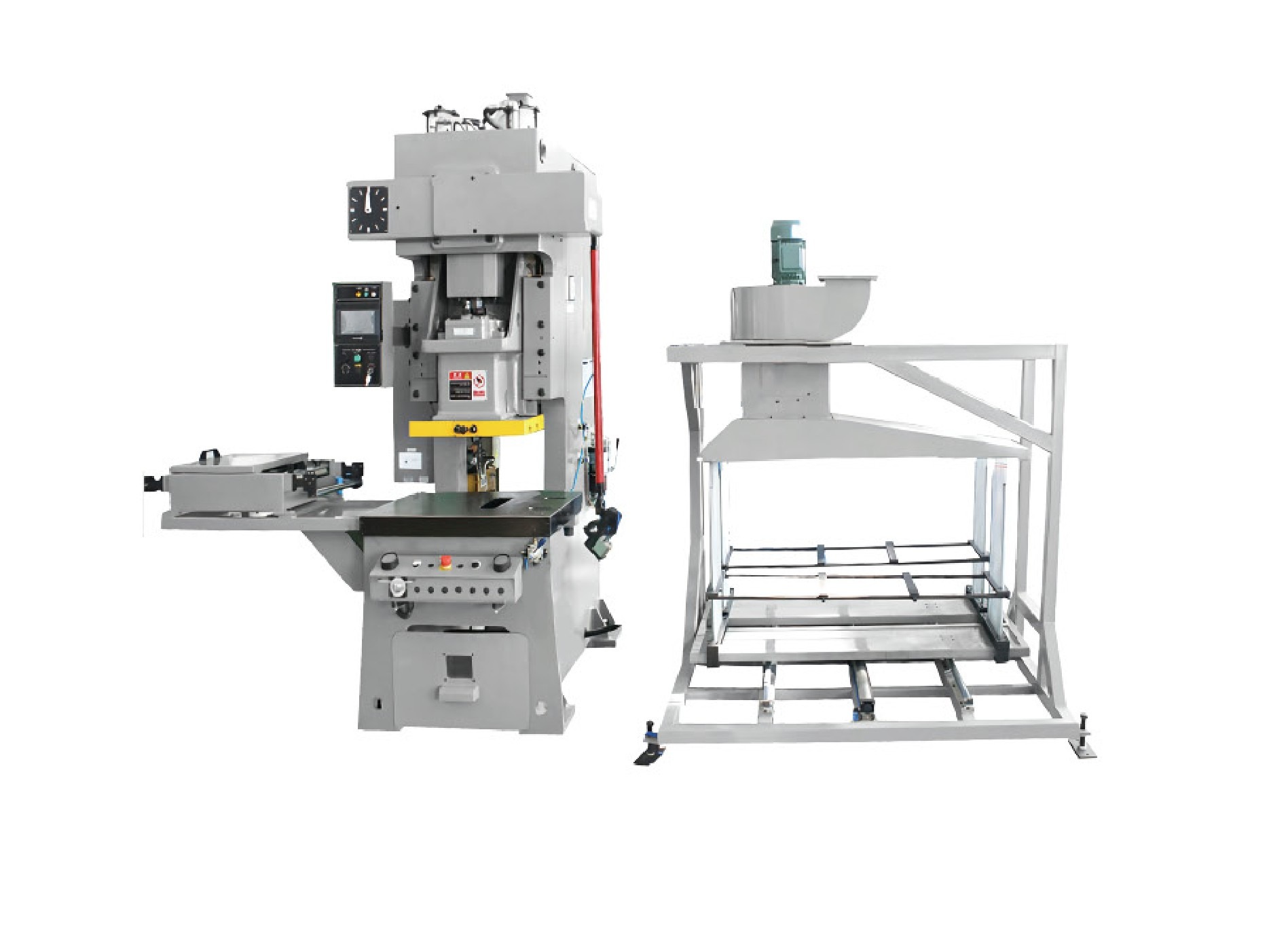
AK Series Open-Type Fin Press
An open-type high-speed precision fin press line for the refrigeration industry, with PLC and rotary-encoder control, variable-frequency drive and hydraulic overload protection.

machines
CNC Spin-Shrinking Machine for Copper & Aluminum Tube Ends
A CNC two-axis spinning machine that necks down (shrinks) the ends of copper and aluminum tubes, with automatic feeding and unloading.
Get a Quote